Showing posts with label ente. Show all posts

Tuesday, May 18, 2010

ME P.1110 Part 4 :Canard wings continued...

Before proceeding further with the wing shaping, you'll want to make some small adjustments to the way the wing is structured.  These adjustments are aimed to make for a less messy boolean operation later on.

To start things off, look at the image above.  The yellow cube with the red arrow pointing to it is a point or vertex on the fuselage.  It would be a good idea to align one segment of the wing to that point.  In this case, the wing segment is circled in red.  I start by getting the Y and Z coordinates of the point I mentioned, then writing it down on a piece of paper (or on a text editor).

Then, I temporarily hide the fuselage to be able to select the points that make up the segment that I encircled in the previous image.

With all three points selected, I bring up the "Align Selected Vertices" dialog box of Metaseq.  I then select the Y and Z checkboxes.  If the Y and Z coordinates are already available in the MIN/MAX button selections, click those.  If not, then manually re-type them on their respective position text boxes.

If done correctly, it should look like the image above.

Do the same for segment indicated above.  Align it with the vertex indicated by the red arrow.

And again, for the segments indicated by the arrows in the image above... 

All done.

After doing those adjustments, the chord (or is it foil?) of the wing will now be a bit deformed.  You will need to reshape it a bit as indicated above.

Now, go to the front view display, then thin out the right edge of the wing as indicated in the picture.  Try to match the way the wing tapers down in the picture.


Done!


Now select the points indicated in the picture above.  Then, by using a combination of resize + move along the Z axis adjust the size and position of the wingtip to match the drawing.


Next, we'll need to round out the wing tip.  Start by slicing a vertical strip using the knife tool at the points indicated by the arrows indicated above.  Then select and join the vertices encircled above.

If done correctly, it should look like the image above.

Here's how it looks so far.

Notice that the segments we tried to align early on are now again misaligned.  That's okay... It will be easy to re-align once more after we do the boolean operation later on to remove the part of the canard hidden inside the fuselage.

Thursday, May 13, 2010

ME P.1110 Part 3 :Making the canard wings

Before starting to work on new objects, I always "lock" the current object to prevent any accidental modifications.

In addition to locking the fuselage object, I'll assign a meaningful name to it.  In this case, "fuselage".  Also, while I'm at it, I might as well change its color to make it easier to identify.


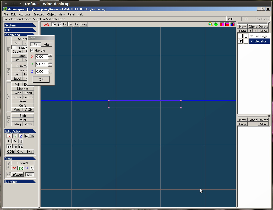
To start with the Canard wing creation, I create a new object called, "elevator".

 I then add a new Cube object.  Unlike the cylinder object, I choose to use the default settings.


 Next, from the top-view panel, move the cube so that it covers just the right  canard wing.  Make sure the left edge of the cube lies inside the fuselage.


Now, in your mind, draw an imaginary line along the front  edge of the canard wing going towards the fuselage until it intersects the left edge of the cube.  Then, move the bottom edge of the cube so that it meets the point where the imaginary line intersects with the left edge of the cube.

Do the same for the rear edge of the canard. Move the top edge of the cube so that it meets the point where the imaginary line of the rear edge meets the left edge of the cube.

Lastly, move the right edge of the cube to the left so that it touches the right edge of the canard.


That was really hard to describe....   Anyway, if done correctly, you should have something similar to the image above.


Now, switch to the front view panel.   Move the top edge of the cube so that it touches the highest point of the top of the canard.  Do the same for the bottom edge of the cube with the lowest point of the canard.


If done correctly, you should have something that looks like the image above.


The next step would be to reshape the cube to form a foil (or whatever you call it).  Start by switching to the side view panel.  Then to make it easier to see what you're doing, 'hide' the Fuselage object as well as the background diagram.


Using the knife tool, make two vertical slices - one near the left edge of the canard, and one between the center and the right edge of the canard.


Now switch to the perspective view.  Notice that I've encircled the four corners of the cube.  The two vertices in each of the four encircled corners should be joined together.


If done correctly, it should look like the image above.


Now, go back to the side view.  Then, move the left and right edges of the wing downwards by a small amount. 


If done correctly, it should look like the image above.


Now, using the knife tool, cut a vertical slice just between the left edge of the canard and the left slice you did a while ago.


 Now, resize the slice so to 'round up' the left edge of the canard.


Here's how it should look like.


Now, take a break and go back to the perspective view panel.  Then unhide the 'Fuselage' object to look at the progress so far.

That's all for now...

Monday, May 10, 2010

ME P.1110 Part 2 :Creating the fuselage

Continuing where I left off, I start with creating a basic cylinder shape. At this point, I will put great emphasis in ensuring that the cylinder shape has as many lengthwise 'slices' as possible. Later on, each slice will comprise one connector tab on the model once it's unfolded.


For this, I chose 32 slices. I don't know if that's enough....but I guess I'll find out later on.


Next, I aligned the cylinder to the fuselage of the background (3-view) images. In this case, it was a simple matter of rotating the cylinder 90 degrees along its x-axis.


Once aligned, I proceeded to re-shape the cylinder to closely match the fuselage of the Ente. If you look that the front view, you'll notice that the cross section of the cylinder is not a perfect circle. It is slightly oval shaped.


Now it's time to work shaping the front part of the fuselage. Starting from just behind the canopy, the fuselage gradually starts tapering down. To do this with the cylinder, I use a knife tool to add a new cross section at the point where the fuselage starts to taper down. In this case, as I mentioned, it's just behind the canopy.


Using the scaling tool, I scaled down the front end of the cylinder by a bit --- just enough to match the gradual taper of the cylinder.


Now, notice that the front end of the cylinder is somehow no longer aligned with the front end of the fuselage's side-view drawing.


To fix this, I moved the front end of the cylinder down by just a bit so that the center point aligns with that of the fuselage's.


Repeat the knife+scale+move process until satisfied....
Now, notice that the front end of the cylinder has significantly shrunk in size. But it's still flat.


To fix this, I used the "join vertices" function.


I then applied the same steps for the rear end of the cylinder.


Fuselage done!

My next step would be to work on the canard wings of the Ente.

ME P.1110 Part 1 : Back in business

After a long hiatus from card modeling, I'm back! :)

This time, instead of building other people's models, I have decided to start with my own stuff. This isn't the first time I've made attempts at designing my own models. Unfortunately, the past attempts all had a lot of flaws. Flaws which I hope I will get to correct, or even avoid this time around.

Tools of the trade
Now, to get started, my tools.

For designing card models, you need 3 tools:
  1. Modeling software - There are plenty to choose from. But for most of my entries, I will be using Metasequoia. Why Metasequoia? Well, because I already chucked in $45 for a license two years ago, when I first started to design my own stuff. It would be a pity to let $45 go to waste. Anyway, there are two free and in my opinion equally powerful (or even more powerful) alternatives -- Google Sketchup and Blender3d. If I encounter a major obstacle in Metasequoia later on, maybe I'll consider jumping to one of those two. But for now, it's Meta for me.
  2. Unfolding software - You'll need this to convert your 3d model into a 2d diagram that is ready to cut out, fold and glue together. Again, there are plenty to choose from. However, I'm using Pepakura, simply because this was the only available unfolder 2 years ago, and I already popped $38 for a license...hehehe....miser. Unfortunately, unlike modeling software, where there are free alternatives, I only know of one free alternative unfolder. I forgot its name though. Other options for unfolders are Ultimate Papercraft 3d and the Waybe plugin for Google Sketchup.
  3. Some painting software - Your 3d model will not elicit oohs and ahhs from your friends if they're just plain uncolored cardboard. (Well, if your friends are also card modelers, then yeah, you will be getting oohs and ahhhs even if your model is done in plain uncolored cardboard....) Anyway, you'll need some painting software to design your textures so that your models will look like the actual object they represent. I use both GIMP and Inkscape.
Additionally, you'll need some 3-view drawings to base your designs from. I get mine mostly from the Luft'46 website. I've a couple of books about Luftwaffe WW2 aircraft which also contain really nice 3-view drawings. But since my interest lies mostly on the what-if's aircraft of the Luftwaffe, I'll be sticking with the 3-views from Luft'46.

Getting started
Damn... after being away from Metaseq for 2 years, I've almost completely forgotten how to use this program. After staring blankly at the screen, I managed to re-learn the basic commands and steps.

For this exercise, I chose to model the Messerschmitt ME P.1110 'Ente'. It has a relatively simple, clean shape with no complex surfaces save for those nacelles on the side of the fuselage.

The first step involves saving a copy of the 3-view, then cutting it up into three separate bitmaps that represent the front, top and side of the model.

Firing up Metasequoia


I then fire up Metasequoia. Under Metaseq's default view, it will be very difficult to create an accurate model, even if you've got a 3-view design to choose from.


Remember the 3 images that I cut up from the original 3-view image? Metaseq's display can be divided into 4 subpanels. Each subpanel can be configured to display a particular angle of your model. In my case, I chose to display the top, side, front and perspective views respectively.

I guess that's it for now. More later.