Friday, April 19, 2013

Focke-Wulf VTOL - Part 7

Some more progress!

For this update, I worked on the exhaust vents for the propellers.

Creating the exhaust vents


If you recall in my earlier posts, one of the leftovers from the Boolean operations I did in creating the hole on the fuselage was the bottom cover of the fuselage.

I did a Boolean subtract operation to cut the engine base from the fuselage bottom cover.

I then took the knife tool to divide the bottom cover into strips.  For consistency, I didn't do any fancy Metaseq voodoo.  I just made some guestimates and hoped for the best.

After cutting the strips, I rotated each by 70 degrees.


This is how it turned out.

How it looks so far


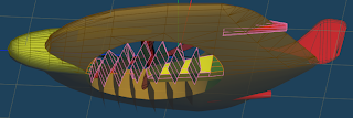
Here's how the exhaust vents look when attached to the main model

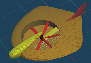
Top view. :)

To do

  • Landing Gears
  • Wheel Wells
  • UV Mapping


Thursday, April 18, 2013

Focke-Wulf VTOL - Part 6

A very, very short update.
I've been ridiculously busy with work lately that I barely have time to extract enough brain juice to resume my design.

But over the weeks, I've done very small steps.  A polygon here, a vector there, a slice here, a slice there.

Eventually, I was able to finish the propeller shaft, propellers and base.

I'm afraid I was not able to record the steps I went through to produce this.

But I should be able to make a write-up on those steps when I get more time.

But for now, here's the latest picture of the model:


And here's a picture of the spinner assembly:

I'll try to put provisions that would allow the spinners to rotate. :)

じゃ、またね。

Wednesday, January 2, 2013

Focke-Wulf VTOL - Part 5

Now on to the rudder!

Design Goal

For the rudder, I want to create a wireframe that will produce a cardboard model that looks somewhat like the image above.

This will be an experiment for me so I'm not sure if this will work out.   If it does work out, I'll be using this for making the wingtips of my future models.

Time to whip out the knife tool again!

Initial Steps


I start by freezing the low poly model to produce the wireframe above.

As always, there's a need to reduce the number of edges, courtesy of the Knife Tool.

Making the Petals


Using the Knife Tool, I've made some small slices on the edges of the rudder.  These will be the "petals".

Then, using manual vertex joins, I produced the image above.  Looks good so far.

Here's a picture of the progress.

I'm not happy with the vertical slice shown above.  I'll be using the knife tool to angle the slice a bit.  This will make the card model assembly easier later on.

Much better!

Joining the Rudder to the Fuselage

To join the rudder to the fuselage, I plan to make something similar to the cockpit-rudder joint.


Nothing special here.  Just a bunch of Boolean intersects and cleanups.

That's basically it for the rudder.

Next I'll start working on the engine.


Tuesday, January 1, 2013

Focke-Wulf VTOL - Part 4


Now to work on the cockpit!

Design Objective


The picture above shows how I want the Cockpit to mate with the fuselage.  This should allow the cockpit to align properly with the fuselage.

Making the Cut


Preparations...

To achieve the design objective, I start by performing two Boolean operations.


First, I get the intersection of the cockpit with the fuselage. (Fuselage = Fuselage # Cockpit)


Again, it's a mess!  The picture above shows the resulting intersect operation after cleanup.


Now, I get the intersection of the fuselage with the cockpit. (Cockpit = Cockpit # Fuselage)


And here's how it looks like after cleaning up the mess that the Boolean operation left behind.

Removing the Unwanted Faces/Surfaces

With the Boolean outline cleaned up, it's time to delete the parts of the Cockpit and the Fuselage to allow both parts to mate.

Here's how the fuselage looks like.


And here's how the cockpit looks like.


Finally, here's how the model looks so far.