Sunday, May 27, 2012

Henschel HS-132 - Part 12

Last week, I stopped working after finishing the front landing gear wheel wells.
Now I'm going to start working on the rear wheel wells.

As in my last post, I start by cloning the rear landing gears, and "raising" the cloned landing gear by rotating along the Z-Axis.  You may notice on the picture above that the gear shaft kinda bulges out of the wings.  This was intentional.  I had to make the landing gear shaft a bit "fat" since I'll be printing this on card stock.   Card stock is difficult to roll very thin.  As a compromise, I made the shafts "fat" to allow for easier rolling.

Now, I've created the rear wheel well template what I'll use to carve out the actual wheel wells.

Here's what I ended up with after subtracting the rear wheel well template from the wing. 
Now it's time to make the wheel covers.  I'll do this by getting the intersection between the wheel well template and the wing.

And here we are... what a mess!  I sure wish that some day, O. Mizuno (the guy who wrote Metaseq) would create his own BOOLEAN operation plugin to replace the old one.  

Now for the clean up process.  Since I only need to make the wheel covers, I start by removing the unneeded edges and vertices.

To help with the cleanup, I'll un-hide the wing.  Then I'll change the edge colors so that I'll "see" which edge belongs to what object.

To clean up the wheel covers, I'll remove the vertices that have no "partner" vertex with the wing.  This is where having a different edge and vertex coloring helps.  (See picture above.)

And finally, rear wheel wells and covers done!

Sunday, May 20, 2012

Henschel HS-132 - Part 11

Time to work on the wheel wells!
Before I get started, lemme tell you that I think the wheel wells are the most P.I.T.A. part of the model, both to design and to assemble, at least in my opinion.  Not only do they get in the way of fuselage formers/fillets, they also sometimes span two separate objects (e.g. fuselage and wing), AS WELL AS formers/fillets.
But somehow, I don't feel I've designed a complete model if I don't put those wheel wells in.  So I just treat it as a necessary evil.

So here we go.

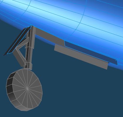
Let's start with the front landing gear wheel wells.  In the picture above, you'll see that I've created the front landing gear.  I've intentionally lengthened the gear shaft because I'll be "snipping" off part of it later when the wheel well is done.

I then simulated "raising" the landing gear up so that I would more or less get an idea how big a wheel well I need to carve out.  So as not to mess up the position of the original landing gear, I cloned it.  I then did a local rotate on the cloned landing gear and placed it on it's "raised" position.

Next, I created a "shape" that I'll use to carve out the wheel well.

Here's how the front wheel well template looks like.  To carve out the wheel well, I'll need to subtract this template from the FUSELAGE using the BOOLEAN operation.

And here's how it looks like (after cleaning up the residual mess that BOOLEAN left behind, of course :-P ).

Making the landing gear covers involves a little bit more work.  I'll need to get the surface of the FUSELAGE where it intersect with the wheel well template.  The easiest way I've found is by using the BOOLEAN INTERSECT function.  The image above shows the result of the operation.

But I want just the covers, so I deleted the other parts of the object.  I then split the two faces above into two separate objects.

Using the local function, I relocated local coordinate center axis, then I did a local rotate along the local X-Axis.

Finally, I did the same for the rear part of the wheel covers.  For this one, I rotated along the local Z-Axis.

And here's how it looks when completed.

The process for the rear wheel wells is basically the same.  But I'll do that one in a later update.

That's it for now.

Sunday, May 13, 2012

Henschel HS-132 - Part 10

Next up, the SC500 bomb.  Simplifying this should be relatively straightforward.

Starting with the frozen wireframe, I'll use the knife tool to remove the unneeded edges.

And we're done. 


Here's how the model looks like so far.  Notice that even though I've removed a lot of edges, the model still retains its curves.  I hope this translates well into the actual paper.

Now for some problems:
First, the bottom part of the engine kinda eats into the fuselage.  Initially, I've considered flattening the bottom part of the engine, and the top part of the fuselage so that it would be easy to mate the engine with the fuselage during assembly.  But doing so would add yet more pieces to the model.  I'll probably go with subtracting the Engine from the fuselage.

Likewise, the SC500 would be carried in a recessed bomb rack.  I'll need to subtract the sc500 from the fuselage as well.


After a couple of boolean operations, here's what I ended up with:

Engine mount.  I guess this would also help align the engine...


Recessed bomb rack.  For now, I'll keep this cavity open. 


Remaining things to do before moving on to skinning:
  • Cut out the wheel wells on the fuselage and the wings.
  • Create the landing gear covers.

Saturday, May 12, 2012

Henschel HS-132 - Part 9

Okay.  Now it's time to work on the BMW003 engine:


As with the fuselage, I'll be using the KNIFE tool to erase segments in key places, taking care to preserve the overall shape of the engine.

So far so good.

For the engine farings, another boolean operation: Faring - (BMW003 + Fuselage).


What a mess!  I'll need to clean this up.  The goal would be to minimize the number of pieces needed to build the engine faring.  I'll use the trusty Knife tool to remove excess edges until I'm left with the minimum amount needed to produce the shape outlined by the red dashed lines on the image above.

And here we go.  In theory, the unfold operation for this part should produce only 3 pieces.


Saturday, May 5, 2012

Henschel HS-132 - Part 8

The process I'll be doing for the elevators are basically the same as the one for the wings.

I got rid of the excess edges using the Knife tool.

Then I did a BOOLEAN operation.  First it was Elevator - Fuselage.  Then I followed it with Elevator - Rudder.

Here's how it looks like when mated with the fuselage and the rudder.

Next I'll be working on the Engines and the Engine Farings.

Henschel HS-132 - Part 7

Now to work on those rudders.

As with the wing and fuselage, I'll be leveraging the mirroring function again.  So I got rid of one of the rudders.

Now, I'm lazy.  I know that the rudder will be symmetrical along its center.  So I take mirroring one further step by getting rid of one half of the rudder, then enabling mirroring along its local axis.

There.  Much better.

Next would be to flatten the side of the rudder getting rid of the horizontal segments. 

Still need to flatten it up a bit more....  I'll be getting rid of all vertical segments save for the ones marked in red.

Now, to simplify the edges.   I want to keep the cut-seams to a minimum, but I also want to preserve the round edges of the rudder. 

Done!  This may look "complicated", but it should unfold pretty well under Pepakura without needing to break it up into multiple pieces.

Now to freeze the object to generate the wireframe on the mirrored side.

Next step --- the elevators!

Tuesday, May 1, 2012

Henschel HS-132 - Part 6

Now to work on the wings.


First, as with the fuselage, I got rid of the left half of the wing and enabled X-Axis mirroring.
Then, using the Knife Tool, I got rid of all of the cross section segments save for the ones at the wingtips.  I'll be saving those for later after I BOOLEAN the wing to the fuselage.  For now, I'll leave them there.

And here is the result:

Looking at the wing cross section, I noticed that the trailing edge of the wing needs a little "sharpening".  I'll need to bring up the Knife Tool again to erase a couple of edges...

After erasing a couple of edges, here's what came out:
Much better!

Now, to use the BOOLEAN function by subtracting the Fuselage from the Wing, producing something like this:


Now, to revisit the wingtip. 
In my previous models, I always used an extra, separate piece for the wing tip.  For this model, I'll experiment with a single piece wingtip.  I'll do this by using some fancy vertex joins which is hard to describe in text.  So just look at the next image. :)


And here's the end result:

I guess that's it for now.